GPS
Project
2018 - April
Measurement
Techniques
Differential Positioning
Relative Positioning
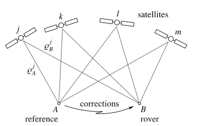
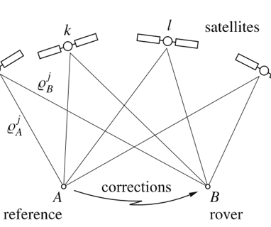
Differential positioning a real-time positioning technique where two or more receivers are used. One receiver, usually at rest, is located at the reference or base station with known coordinates and the remote receivers are fixed or roving and their coordinates are to be determined.
The reference station commonly calculates pseudorange corrections (PRC) and range rate corrections (RRC) which are transmitted to the remote receiver in real time.
The remote receiver applies the corrections to the measured pseudoranges and performs point positioning with the corrected pseudoranges.
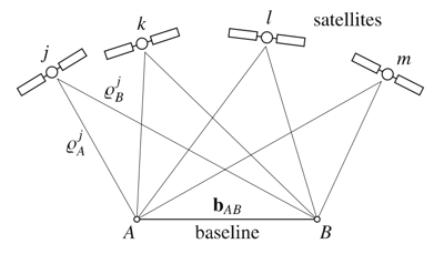
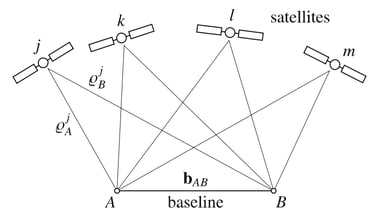
The objective of relative positioning is to determine the coordinates of an unknown point with respect to a known point which, for most applications, is stationary. In other words, relative positioning aims at the determination of the vector between the two points, which is often called the baseline vector or simply baseline.
Relative Positioning Techniques:
Static relative positioning:
In a static survey of a single baseline vector between points A and B, the two receivers must stay stationary during the entire observation session.
Kinematic relative positioning:
In kinematic relative positioning, the receiver on the known point A of the baseline vector remains fixed. The second receiver moves, and its position is to be determined for arbitrary epochs.

Static Relative Positioning
Planning
The first phase of the project is planning in which observation of the satellites is taken place using a program named “SATELLITE AVAILABILITY”. The following steps explain the phase in details.
The First page
open the program:
1. Click “site”.
2. Fill “site” with the name of the project.
3. Fill the latitude, longitude and the height.
4. Choose “the time zone” for the field work.
5. Choose “the cut-off-angle”.
6. Fill “the date” of the workday.
7. Click “OK”.
Page number 2
“Satellite summery site” shows the largest number of satellites in this day can be observed up to 10 satellites in the periods (00:00 to 01:00) and (21:30 to 22:00). Seven satellites were observed during work time (11:00 to 12:00).
Page Number 3
The orbit of all satellites can be seen in “SKY Plot”.
Page Number 4
“Satellite visibility” indicates the period between the times when it comes out in the sky and disappears later.
Page Number 5
“Satellite PDOP/GDOP” shows the amount of PDOP and GDOP. The most accurate positions will generally be computed when the GDOP is low, (usually 8 or less).
Page Number 6
“Satellite elevation” shows the elevation of all satellites and the angle of their height.
Page Number 7
The needed data “Azimuth and elevation for satellites” during the work.
Field Work
By using the two receivers (BASE and ROVER) after planning:
Adjust the BASE receiver which remains stationary at a site with precisely known coordinates.
Turn on the receiver.
Click “Lap” to name the BASE point.
Click “Survey” to choose the technique. choose “static”.
Click “coving” to check the satellites.
After that...
1- Adjust the ROVER receiver in a point with unknown coordinates.
2- Turn on the receiver.
3- Click “Lap” to name the point.
4- Click “Survey” to choose the technique. choose “static”.
5- Setting the time with the BASE time.
6- Click “KPI”.
Wait for 30 minutes…
7- Click “Stop”.
8- Click “Store”.
Processing
Process the collecting data from the field by the app (SKI-PRO)..
Pages number 8 and 9
Open the program:
1. Click “new project” icon.
2. Click “General” icon.
3. Name the project.
4. Choose “the time zone” for the field work.
5. Click “coordinates” icon.
6. Choose a coordinates system (map projection).
7. Click “OK”.
Page number 10
1. Click “import GPS raw data” icon.
2. Put the USP in the PC.
3. Choose the icon “static” then “REF”.
4. Bring the data from the file
5. Click “import”.
Page number 11
Choose the file which has the name of your project, then click “Assign”.
Page number 12
In this page, the location (longitude, latitude) of the two receivers (BASE and ROVER), and the scale are shown.
Page number 13
Click on SE (BASE) for “point properties”:
1. Point ID: name of the point.
2. Point class: choose “Navigated”.
3. The coordinates and the accuracy of the point are shown before the process.
4. Click “OK”.
Page number 14
Click on S1(ROVER) for “point properties”:
1. Point ID: name of the point.
2. Point class: choose “Navigated”.
3. The coordinates and the accuracy of the point are shown before the process.
4. Click “OK”.
Page number 15 and 16
1. Click “the data process” icon.
2. Choose which of them is the BASE and which is the ROVER.
3. Save the point by clicking the right click then click “START”.
4. Processing.
Page number 17
Now, an upside-down triangle appears for the BASE point, and a circle “measured” for the ROVER point.
Page number 18
Click on SE (BASE) for “point properties”:
1. Chose The coordinates type as “GEODETIC”.
2. The coordinates can be changed; however, the accuracy equals ZERO.
3. Click “OK”.
Page number 19
Click on S1 (ROVER) for “point properties”:
1. Chose The coordinates type as “GEODETIC”.
2. The coordinates can NOT be changed, and the accuracy equals ZERO.
3. Click “OK”.
Finally, you have 2 options:
Export the data for general file or Export the data for GIS.
Kinematic Relative Positioning
Planning
The first phase of the project is planning in which observation of the satellites is taken place using a program named “SATELLITE AVAILABILITY”. The following steps explain the phase in details.
The First page
open the program:
1. Click “site”.
2. Fill “site” with the name of the project.
3. Fill the latitude, longitude and the height.
4. Choose “the time zone” for the field work.
5. Choose “the cut-off-angle”.
6. Fill “the date” of the workday.
7. Click “OK”.
Page number 2
“Satellite summery site” shows the largest number of satellites in this day can be observed up to 10 satellites in the periods (00:00 to 01:00) and (21:30 to 22:00). Seven satellites were observed during work time (11:00 to 12:00).
Page Number 3
The orbit of all satellites can be seen in “SKY Plot”.
Page Number 4
“Satellite visibility” indicates the period between the times when it comes out in the sky and disappears later.
Page Number 5
“Satellite PDOP/GDOP” shows the amount of PDOP and GDOP. The most accurate positions will generally be computed when the GDOP is low, (usually 8 or less).
Page Number 6
“Satellite elevation” shows the elevation of all satellites and the angle of their height.
Page Number 7
The needed data “Azimuth and elevation for satellites” during the work.
Field Work
By using the two receivers (BASE and ROVER):
1- Adjust the BASE receiver which remains stationary at a site with precisely known coordinates.
2- Turn on the receiver.
3- Click “Lap” to name the BASE point.
4- Click “Survey” to choose the technique. choose “KINEMATIC”.
5- Click “coving” to check the satellites.
After that...
1- Hold the ROVER receiver in a point with unknown coordinates.
2- Turn on the receiver.
3- Click “Lap” to name the point.
4- Click “Survey” to choose the technique. choose “KINEMATIC”.
5- Setting the time with the BASE time.
6- Click “KPI”.
Wait for ONE minute…
7- Click “Stop”.
8- Click “Store”.
And so on for the rest of points.
Processing
Process the collecting data from the field by the app (SKI-PRO)..
Pages number 8 and 9
Open the program:
1. Click “new project” icon.
2. Click “General” icon.
3. Name the project.
4. Choose “the time zone” for the field work.
5. Click “coordinates” icon.
6. Choose a coordinates system (map projection).
7. Click “OK”.
Page number 10
1. Click “import GPS raw data” icon.
2. Put the USP in the PC.
3. Choose the icon “KINEMATIC” then “REF”.
4. Bring the data from the file.
5. Click “import”.
Page number 11 and 12
It shows in these two pages the period Disconnects between the ROVER receivers and the satellite.
Page number 13
In this page, the location (longitude, latitude) of the BASE receiver and ROVER receivers and the scale before the process are shown.
Page number 14
Click on K7 for “point properties”:
1. Point ID: name of the point.
2. Point class: choose “Navigated”.
3. The coordinates and the accuracy of the point are shown before the process.
4. Click “OK”.
Page number 15
1. Click “the data process” icon.
2. Choose which of them is the BASE and which is the ROVER.
3. Save the point by clicking the right click then click “START”.
4. Processing.
Page number 16
In this page, the location (longitude, latitude) of the two receivers (BASE and ROVER), and the scale are shown AFTER THE PROCESS.
One of the points (point K4) not processed.
Now, an upside-down triangle appears for the BASE point, and a circle “measured” for the ROVER point.
Page number 17
Click on K7 (BASE) for “point properties”:
1. Point ID: name of the point.
2. Point Class: choose "Measured".
3. Choose The coordinates type as “GEODETIC” (j, λ, h).
4. The coordinates and the accuracy of the point will be shown after the process.
5. Click “OK”.
Page number 18
1. Point ID: name of the point.
2. Point Class: choose "Measured".
3. Choose The coordinates type as “GRID” (X, Y, Z).
4. The coordinates and the accuracy of the point will be shown after the process.
5. Click “OK”.
Page number
Finally, you have 2 options:
Export the data for general file or Export the data for GIS.